Three-Phase, High-Voltage, Halogen and Audio Transformers
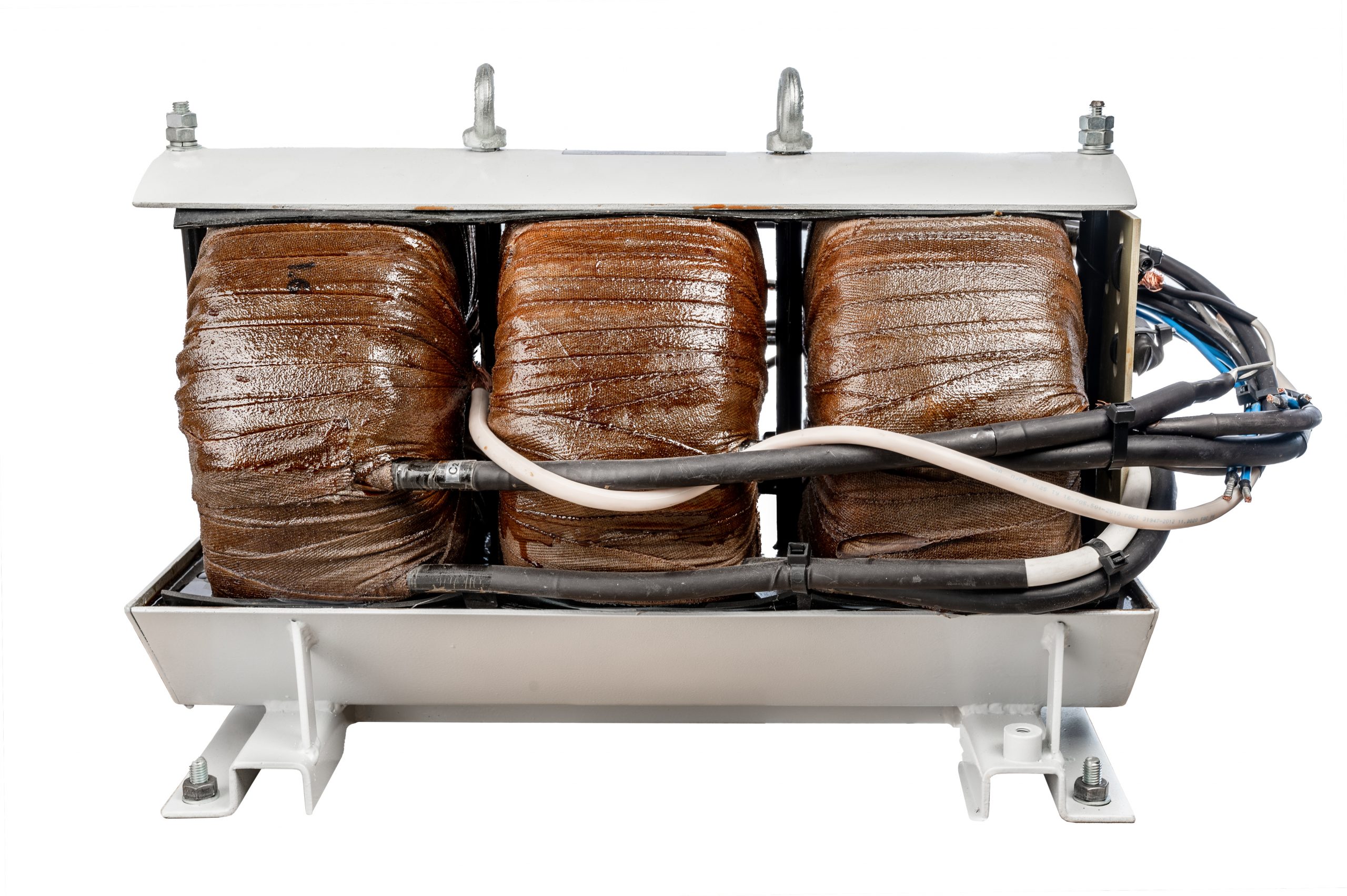
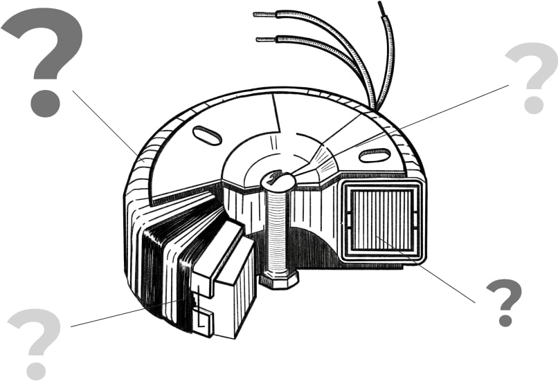
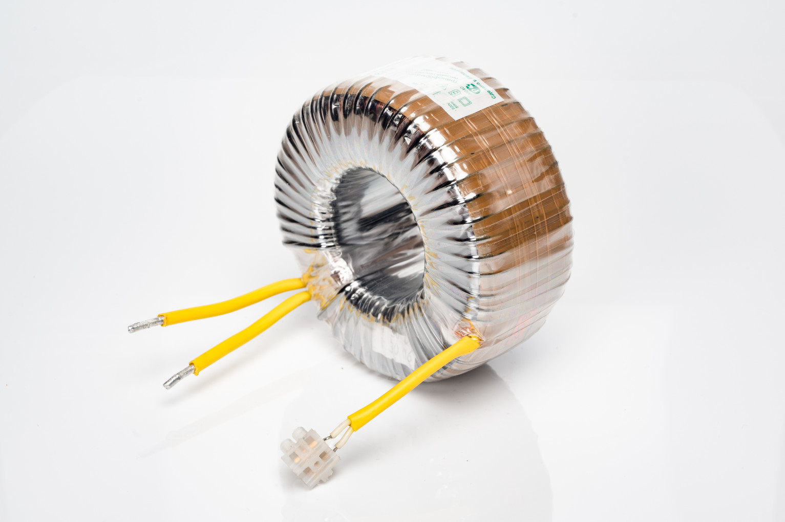
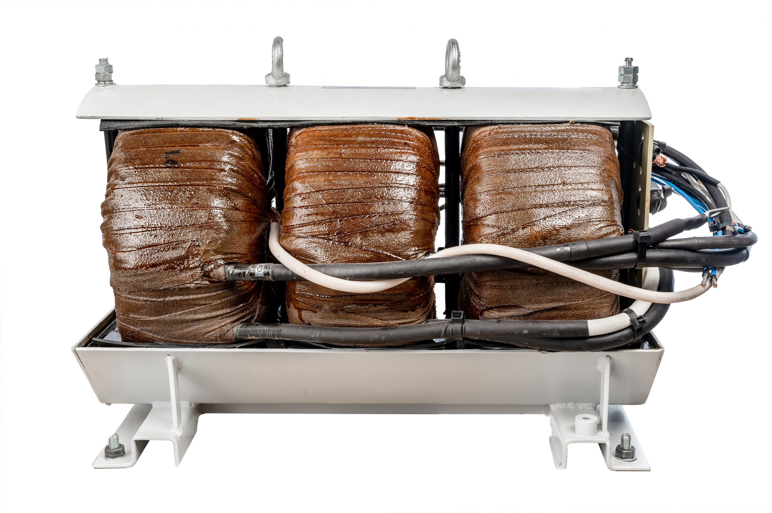
Three-phase transformer – is a static device with three pairs of windings designed to convert voltage and current of one magnitude into voltage and current of another magnitude in a three-phase electrical system. This conversion is carried out using three single-phase toroidal transformers.
High-voltage transformers High-voltage sources (HVS), also known as ignition units or high-voltage ignition transformers, for burners using liquid and gaseous fuels, as well as high-voltage transformers for neon lighting, neon lamps, and advertising signs—also known as neon transformers.
Transformers for powering halogen lamps A step-down transformer for halogen lamps converts the 220 V mains voltage into a low voltage of 6, 12, or 24 V.
Audio transformers Designed to convert audio-frequency voltage and current (20–20,000 Hz). An audio transformer matches the impedance of the audio signal source to the load impedance.
Custom manufacturing
Three-phase transformers Up to 120 kVA, designed for use in industrial and household equipment. Three-phase transformers are assembled from three single-phase toroidal transformers connected in a star, delta, or zigzag configuration. Transformers rated up to 3 kVA are assembled vertically, while those rated above 3 kVA are assembled horizontally. In some cases, a tiered assembly is used.

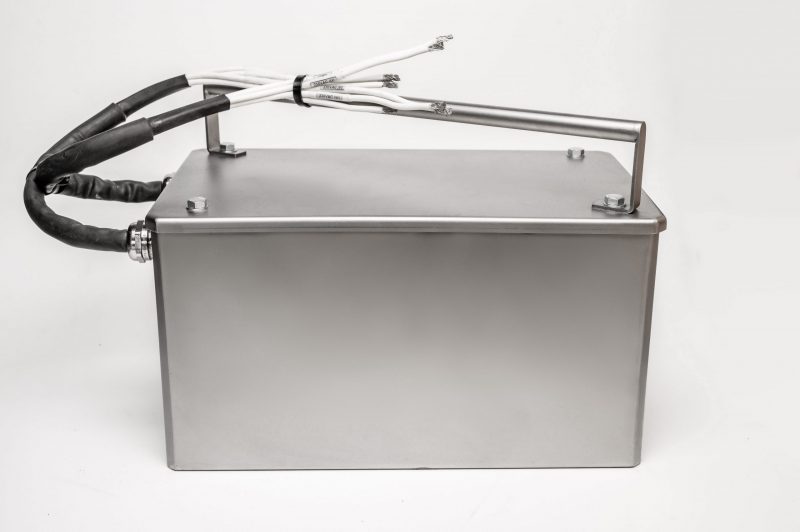
Products whose operating conditions require a high degree of moisture and dust protection (IP rating) are housed in a metal enclosure and fully encapsulated with protective compounds.

Insulation heat-resistance classes: B (130°C), F (150°C), H (180°C).
Optional features:
Temperature sensors, terminal blocks, and wiring panels are installed.
The transformer is insulated using PET-E film, varnished cloth, LES tape, and twill tape.
– Moisture protection: impregnation by dipping in K-115 resin, complete encapsulation with compound, and installation in a protective housing.
– Finished product mounting: transformer mounting dimensions are selected individually for each version.
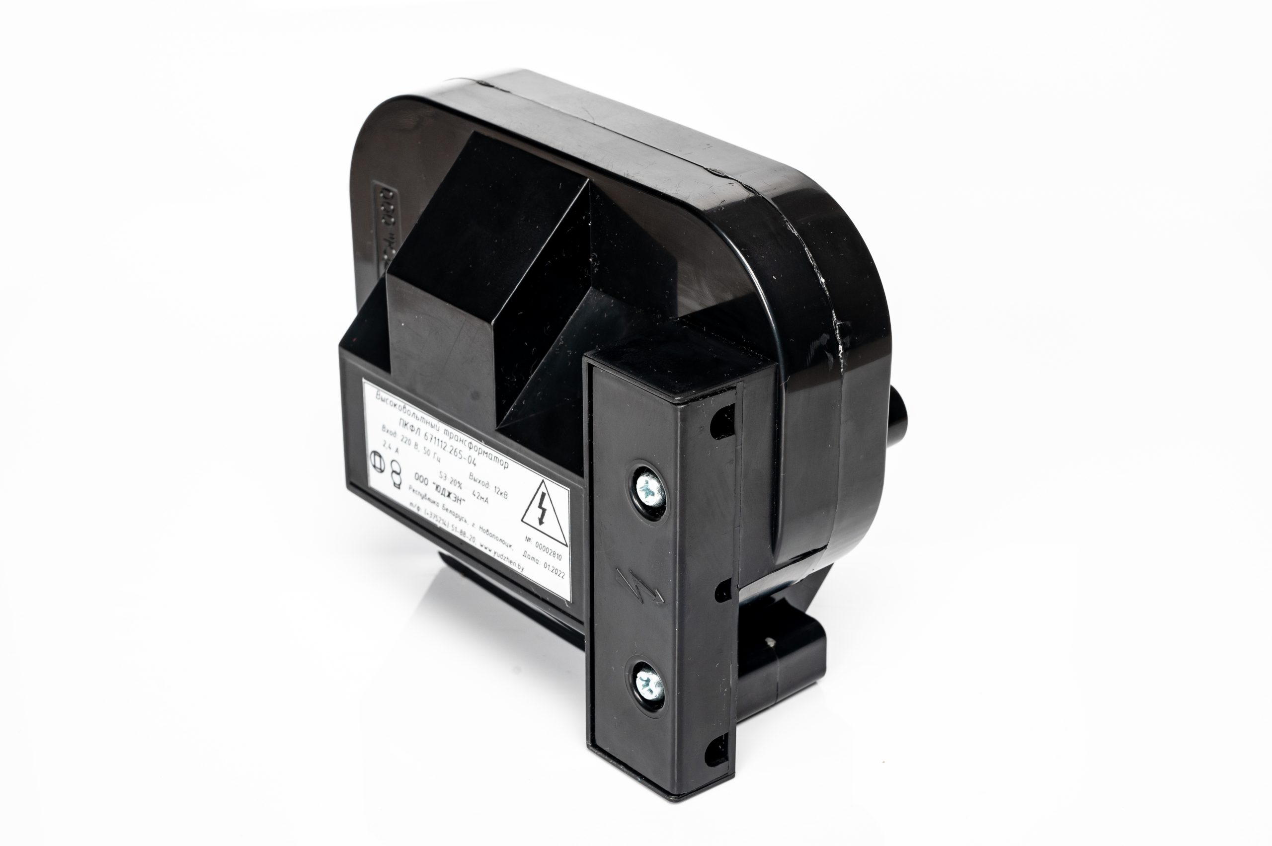
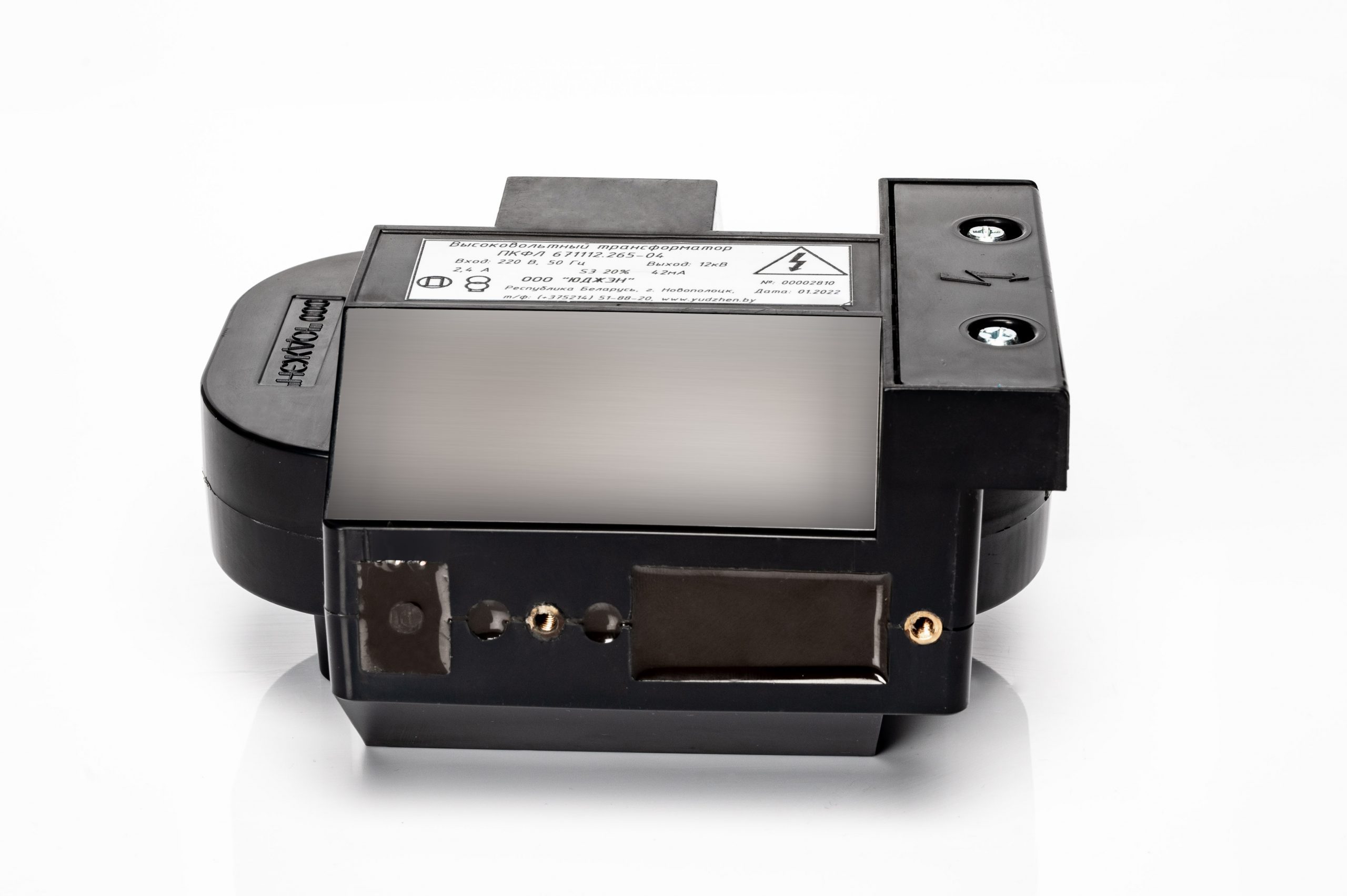
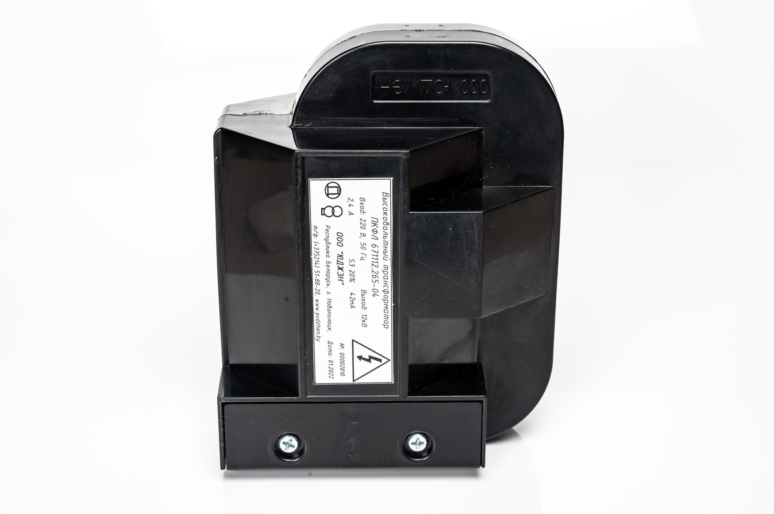
High-voltage transformers – These are electromagnetic voltage transformers—high-voltage power supplies (HVPS)—housed in glass-fiber-reinforced polyamide enclosures and encapsulated with a polymer compound. They are designed to ignite liquid and gaseous fuels in heat-generating equipment such as heat generators, boiler units, and kilns. High-voltage transformers can also be used to power high-voltage neon lamps for advertising signs, etc.
The transformer’s original design ensures reliable operation over a long service life, low heat generation, and low finished-product weight. The one-piece core reduces power consumption by minimizing stray currents. For ease of installation, all electrical terminals are located beneath a single plastic cover.
High-voltage transformers for neon lighting and ignition transformers for burners are durable and offer good chemical and mechanical strength. They are resistant to corrosion and cracking and are easy to install and operate.
PKFL 671112.648-XXXX high-voltage transformers and IVN high-voltage power supplies are designed for operation in locations protected from direct sunlight and water.
High-voltage transformers for neon lighting (neon transformers, electromagnetic transformers for neon lamps, transformers for neon advertising, neon sign transformers) are designed to power neon lamps (neon tubes). These transformers are used in outdoor advertising and are also widely used in other fields, such as architectural illumination of buildings and other types of decorative and artistic lighting.
| PKFL 671112.648-XXXX high-voltage transformer for neon | 25/30 mA | 35/45 mA`”text-align: center;” colspan=”2″>50/60 mA | ||||||||
| 0225 | 0325 | 0425 | 0525 | 0625 | 0235 | 0335 | 0435 | 0250 | 0350 | |
| Operating temperature | -40…+50 | |||||||||
| Rated primary voltage, V | ~220 V, 50 Hz | |||||||||
| Rated secondary voltage, V | 2000 | 3000 | 4000 | 5000 | 6000 | 2000 | 3000 | 4000 | 2000 | 3000 |
| Primary winding current at rated load, A, max. | 0,25 | 0,36 | 0,49 | 0,6 | 0,72 | 0,35 | 0,35 | 0,66 | 0,48 | 0,72 |
| Rated secondary current, mA | 25 | 35 | 50 | |||||||
| Overall dimensions, mm | 151 × 120 × 84 | |||||||||
Example: High-voltage transformer PKFL 671112.648-0525 indicates an output voltage of 5 kV and a rated operating current of 25 mA.
Attention!
Gas-discharge (neon) tubes are custom-made products. They may have arbitrary shapes, numbers of bends, lengths, and diameters, as well as electrodes from different manufacturers. The tubes are produced using equipment with varying vacuum-pumping and inert-gas-filling parameters.
All the factors listed above affect the electrical parameters of neon lamps, and the resulting changes can be significant. Therefore, using load tables alone is insufficient for accurate load calculation. These tables should be used for reference only. After connecting the load to the transformer, the current in the secondary circuit must be measured.
The current in the transformer’s secondary circuit must not exceed the rated value by more than 5% or fall more than 10% below it. The mains voltage must be 220 V.
| Rated operating current (mA) | Maximum short-circuit current (mA) | 25 | 30 | 22,5 – 26,3 |
| 35 | 45 | 31,5 – 36,8 | ||
| 50 | 60 | 45 – 52,5 |
Use a clamp meter to measure the secondary-circuit current. Avoid underloading neon transformers: an incorrectly selected load changes the transformer’s operating parameters and may cause premature aging and failure.
Reference tables for calculating load length for neon transformers.
| Outer tube diameter, mm | 10 | 12 | 15 | 18 | ||||
| Gas pressure in the tube, mmHg | 12 | 10 | 8 | 7 | ||||
| Transformer secondary voltage, volts | Electric meters | |||||||
| 2000 | 1,22 | 1,52 | 2,13 | 2,44 | ||||
| 3000 | 2,13 | 2,74 | 3,66 | 4,27 | ||||
| 4000 | 2,74 | 3,66 | 4,88 | 5,79 | ||||
| 5000 | 3,66 | 4,57 | 6,1 | 7,01 | ||||
| 6000 | 4,88 | 5,79 | 7,32 | 8,53 | ||||
| Neon gas (Ne) | ||||
| Outer tube diameter, mm | 10 | 12 | 15 | 18 |
| Gas pressure in the tube, mmHg | 13 | 12 | 10 | 8 |
| Transformer secondary voltage, volts | Electric meters | |||
| 2000 | 1,22 | 1,52 | 2,13 | 2,44 |
| 3000 | 1,83 | 2,44 | 3,05 | 3,55 |
| 4000 | 2,44 | 3,05 | 3,96 | 4,88 |
| 5000 | 3,05 | 3,66 | 5,18 | 5,79 |
| 6000 | 3,96 | 4,88 | 6,1 | 7,01 |
For calculations using the tables, the physical length of the expected load must be converted into electrical length. The electrical length of all tubes connected in the circuit is the sum of the electrical lengths of each individual tube.
The electrical length of the tube is the sum of its linear length (from the ceramic ring of one electrode to the ceramic ring of the other electrode) plus 0.3 meters, which compensates for the voltage drop across the electrodes.
High-voltage transformers for igniting burners PKFL 671112.265-03 and PKFL 671112.265-04 (high-voltage power supplies—IVN).
Designed for igniting liquid and gaseous fuels in heat-generating installations (heat generators, boiler units, kilns, etc.).
Single-phase, encapsulated, enclosed design.
Designed for operation in locations protected from direct sunlight and water.
An induction transformer with two terminals, intended to ignite fuel (gas, kerosene, diesel fuel, etc.) between two electrodes or two igniters.
Main technical specifications of high-voltage transformers for ignition
| Burner ignition transformer | PKFL 671112.265-03 | PKFL 671112.265-04 |
| Operating temperature | -40…+50 | |
| Rated primary voltage, V | ~220+15-10, 50–60 Hz | |
| Rated secondary voltage, V | ~7000+750 | ~12000+200 |
| Primary winding current at rated load, A, max. | 1,1 | 2,4 |
| Rated secondary current, mA | 30 | 42 |
| Duty cycle (PV), % | 20% | |
| Cycle duration, s | 180 | 120 |
| Continuous arc operation time, min | 7 | 5 |
| Overall dimensions, mm | 151 × 120 × 84 | |
| Weight, kg | 3,3 | 3,2 |
Step-down transformer for halogen lamps (light sources) is a device that converts a 220-volt mains supply into a low voltage of 6, 12, or 24 volts. Transformers currently available are divided into two types:
- electromagnetic transformers;
- electronic transformers for halogen lamps.
Halogen lighting fixtures and lamps are widely used in office, commercial, and residential lighting. Compared with traditional incandescent bulbs, halogen lamps offer higher luminous efficacy and excellent color rendering, ensuring visual comfort. Halogen lamps last 2–4 times longer than incandescent bulbs. Halogen light sources have a wide range of applications: in addition to general lighting, they are used for accent, retail, and decorative lighting.
Halogen lamps are divided into two categories:
1) Lamps designed to operate on a 220 V AC supply. They can be connected directly to a standard power supply without any additional equipment.
2) Low-voltage lamps designed to operate with 6, 12, or 24 V power supplies or transformers. To operate from a standard 220 V mains supply, they require power adapters—transformers for halogen lamps.
Recessed fixtures with these halogen lamps are often found in offices, private homes, and apartments. They are also used for decorative lighting in store displays and furniture. The main advantages of low-voltage halogen lamps are their longer service life and the high level of safety provided by the low supply voltage. However, to take full advantage of these benefits, the right transformer must be selected for the lamps.
The use of halogen lamps can significantly increase illumination while reducing energy consumption compared with traditional incandescent lamps. A step-down voltage transformer is required to power low-voltage halogen lamps. Halogen lamps designed for a 220 V supply have seen limited use due to their high cost and short service life.
Toroidal transformers for 12-volt halogen lamps—also called step-down transformers for “halogen lights” or transformers for halogen lamps—are widely used today. To purchase electromagnetic transformers for halogen lamps, contact our specialists. They will help you select the right products for your needs. Wholesale deliveries of step-down transformers, including custom orders, are available.
YUKON RU LLC manufactures electromagnetic step-down toroidal transformers for powering 12 V halogen lamps, with ratings from 20 to 600 VA, designed for a 220 V, 50 Hz mains supply. The maximum transformer temperature rise is 45°C.
| № | Transformer brand | Technical specifications of the transformer for halogen lamps | |||||
| P, VA | Dimensions dn/dvnh, mm |
Mass, not more than, kg |
t Overheating, °C | No-load current, mA | No-load voltage, V | ||
| 1 | TTP-100-0.02 | 20 | 25/72-30 | 0,39 | 28,5 | 7 | 13,5 |
| 2 | TTP-100-0.02-TM | 20 | 25/72-30 | 0,39 | 28,5 | 7 | 13,5 |
| 3 | TTP-101-0,035 | 35 | 27/76-33 | 0,47 | 40,9 | 8 | 12,75 |
| 4 | TTP-101-0,035-TM | 35 | 27/76-33 | 0,47 | 40,9 | 8 | 12,75 |
| 5 | TTP-102-0.05 | 50 | 27/81-37 | 0,66 | 39,8 | 11 | 12,4 |
| 6 | TTP-102-0.05-TM | 50 | 27/81-37 | 0,66 | 39,8 | 11 | 12,4 |
| 7 | TTP-102-0,06 | 60 | 25/82-39 | 0,71 | 41,7 | 11 | 12,1 |
| 8 | 60 | 25/82-39 | 0,71 | 41,7 | 11 | 12,1 | |
| 9 | 80 | 36/94-43 | 1,01 | 40,8 | 15 | 12,55 | |
| 10 | 80 | 36/94-43 | 1,01 | 40,8 | 15 | 12,55 | |
| 11 | 105 | 35/97-44 | 1,18 | 42,1 | 15 | 12,45 | |
| 12 | TTP-104-0,105-TM | 105 | 35/97-44 | 1,18 | 42,1 | 15 | 12,45 |
| 13 | TTP-105-0,15 | 150 | 30/110-47 | 1,66 | 43,6 | 17 | 12,4 |
| 14 | TTP-105-0,15-TM | 150 | 30/110-47 | 1,66 | 43,6 | 17 | 12,4 |
| 15 | TTP-106-0,2 | 200 | 44/127-46 | 2,11 | 43,6 | 20 | 12,275 |
| 16 | TTP-106-0,2-TM | 200 | 44/127-46 | 2,11 | 43,6 | 20 | 12,275 |
| 17 | TTP-106-0,25 | 250 | 42/124-55 | 2,68 | 45,3 | 25 | 12,5 |
| 18 | TTP-106-0,25-TM | 250 | 42/124-55 | 2,68 | 45,3 | 25 | 12,5 |
| 19 | TTP-107-0,3 | 300 | 53/136-58 | 3,10 | 45,5 | 30 | 12,5 |
| 20 | TTP-107-0,3-TM | 300 | 53/136-58 | 3,10 | 45,5 | 30 | 12,5 |
| 21 | TTP-108-0,4 | 400 | 49/148-59 | 3,97 | 45,8 | 35 | 12,2 |
| 22 | TTP-108-0,4-TM | 400 | 49/148-59 | 3,97 | 45,8 | 35 | 12,2 |
| 23 | TTP-109-0,5 | 500 | 47/158-60 | 4,78 | 46,6 | 40 | 12,15 |
| 24 | TTP-109-0,5-TM | 500 | 47/158-60 | 4,78 | 46,6 | 40 | 12,15 |
| 25 | TTP-109-0,6 | 600 | 55/160-73 | 5,99 | 46,5 | 50 | 12,275 |
| 26 | TTP-109-0.6-TM | 600 | 55-160-73 | 5,99 | 46,5 | 50 | 12,275 |
Audio transformers are manufactured using toroidal magnetic cores and are intended for use in the audio circuits of radio-electronic equipment, including communication devices, public-address systems, wired broadcasting systems, and impedance-matching circuits.
An audio transformer requires a particularly careful approach to circuit and design solutions. Its primary purpose is to match the impedance of the audio signal source to the load impedance. This matching reduces electrical signal losses during transmission to the output stage.
When converting the input signal voltage, the transformer must remain operational over a wide frequency range of 20–20,000 Hz.
Due to the specific application of such transformers, the development of a prototype is mandatory. Based on the transformer test results, the Customer decides whether to manufacture a production batch. Products that fail the tests are not approved for production.
When designing the transformer, the power drawn from the secondary windings and the frequency range are taken into account. The required electrical steel strip thickness is selected, and measures are taken to reduce parasitic capacitance and increase flux linkage with the secondary windings. The following electrical steel strip thicknesses are used for the magnetic cores: 0.08 mm, 0.15 mm, and 0.3 mm.
Opcionalno:
– The transformer is insulated using PET-E film.
– Moisture protection: impregnation with ML-92 varnish or KP 55-5 compound.
– Finished product mounting options: standard mounting (metal or plastic washer, gasket, bolt, nut); potting the central opening with compound, leaving a mounting hole; potting the central opening with compound and any mounting elements (internal bushing); DIN-rail mounting; mounting on a metal base using four mounting holes.
Download Product Catalogue
Still Have Questions?
Still Have Questions? We Will Advise You!